Next: Hydraulic pipe system Up: Simple example problems Previous: Seepage under a dam Contents
In this section the capacitance of a cylindrical capacitor is calculated with inner radius 1 m, outer radius 2 m and length 10 m. The capacitor is filled with air, its permittivity is \epsilon_0=8.8542 \times 10^{-12} ~ C^2/Nm^2. An extract of the input deck, which is part of the test example suite, is shown below:
*NODE, NSET=Nall
...
*ELEMENT, TYPE=C3D20, ELSET=Eall
...
*NSET,NSET=Nin
1,
2,
...
*NSET,NSET=Nout
57,
58,
...
*SURFACE,NAME=S1,TYPE=ELEMENT
6,S3
1,S3
*MATERIAL,NAME=EL
*CONDUCTIVITY
8.8541878176e-12
*SOLID SECTION,ELSET=Eall,MATERIAL=EL
*STEP
*HEAT TRANSFER,STEADY STATE
*BOUNDARY
Nin,11,11,2.
Nout,11,11,1.
*EL FILE
HFL
*SECTION PRINT,SURFACE=S1
FLUX
*END STEP
As explained in Section ![[*]](crossref.png) the capacitance can be
calculated by determining the total heat flux through one of the capacitor's
surfaces due to a unit temperature difference between the surfaces. The material in between the
surfaces of the capacitor is assigned a conductivity equal to its
permittivity. Here, only one degree of the capacitor has been modeled. In
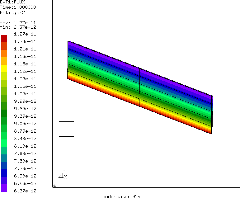
axial direction the mesh is very coarse, since no variation of the temperature is expected. Figure
shows that the heat flux at the inner radius is
1.27 \times 10^{-11} W/m^2 . This corresponds to a total heat flow of
7.98 \time 10^{-10} W. The analytical formula for the capacitor yields
2 \pi \epsilon_0 / \ln (2) = 8.0261 \time 10^{-10} C/V.
the capacitance can be
calculated by determining the total heat flux through one of the capacitor's
surfaces due to a unit temperature difference between the surfaces. The material in between the
surfaces of the capacitor is assigned a conductivity equal to its
permittivity. Here, only one degree of the capacitor has been modeled. In
axial direction the mesh is very coarse, since no variation of the temperature is expected. Figure
shows that the heat flux at the inner radius is
1.27 \times 10^{-11} W/m^2 . This corresponds to a total heat flow of
7.98 \time 10^{-10} W. The analytical formula for the capacitor yields
2 \pi \epsilon_0 / \ln (2) = 8.0261 \time 10^{-10} C/V.
The total flux through the inner surface S1 is also stored in the .dat file because of the *SECTION PRINT keyword card in the input deck. It amounts to -2.217 \times 10^{-12} W. This value is negative, because the flux is entering the space in between the capacitor's surfaces. Since only one degree was modeled, this value has to be multiplied by 360 and yields the same value as above.