Next: Theory Up: Simple example problems Previous: Optimization of a simply Contents
This example illustrates the use of the *REFINE MESH keyword card in order to
refine a tetrahedral mesh based on some solution variable. The structure is a
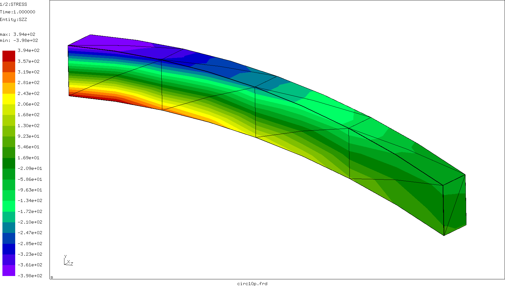
curved cantilever beam (Figure ![[*]](crossref.png) ) meshed very coarsely using C3D10
elements. The left side of the beam is completely fixed in z-direction, the
lower left node is furthermore fixed in x and y, the lower right node in
y. A load of 9 force units is applied to the nodes in the right face of the
beam in +y direction. This leads to the normal stresses in z shown in the
Figure. The beam experiences bending leading to tensile stresses at the bottom
and compressive stresses at the top. The input deck of the beam (circ10p.inp)
is part of the CalculiX test suite.
) meshed very coarsely using C3D10
elements. The left side of the beam is completely fixed in z-direction, the
lower left node is furthermore fixed in x and y, the lower right node in
y. A load of 9 force units is applied to the nodes in the right face of the
beam in +y direction. This leads to the normal stresses in z shown in the
Figure. The beam experiences bending leading to tensile stresses at the bottom
and compressive stresses at the top. The input deck of the beam (circ10p.inp)
is part of the CalculiX test suite.
Here, only the step information in the input deck is reproduced:
*STEP
*STATIC
*CLOAD
LOAD,2,1.
*NODE PRINT,NSET=FIX,TOTALS=ONLY
RF
*SECTION PRINT,SURFACE=Sfix,NAME=SP1
SOF,SOM
*NODE FILE
U
*EL FILE
S
*REFINE MESH,LIMIT=50.
S
*END STEP
It illustrates several possibilities to obtain the reaction forces. One way is to use the *NODE PRINT keyword card to request the storage of RF in the .dat file. It acts on a node set, in this case all nodes on the left surface of the beam. The parameter TOTALS=ONLY indicates that only the sum of the forces should be printed, not the individual contributions. The *NODE PRINT option works well if the adjacent elements of the nodal set are not subject to distributed loads, neither surface distributed loads (pressure) nor volumetric distribute loads (gravity, centrifugal forces). Else the value printed for RF will include part of these latter forces.
A second possibility is to define a facial surface and use SOF and SOM underneath the *SECTION PRINT card in order to request the forces and moments on this surface. The surface Sfix consists of all faces in the left surface of the beam. The forces and moments are obtained by integration across the surface.
The output in the .dat-file looks like:
 total force (fx,fy,fz) for set FIX and time  0.1000000E+01

       -9.372063E-13 -9.000000E+00  3.127276E-12


 statistics for surface set SFIX and time  0.1000000E+01

   total surface force (fx,fy,fz) and moment about the origin(mx,my,mz)

    2.454956E+00 -7.226251E+00  1.377949E+01  7.236961E+01 -5.740438E+00 -4.957194E+00

   center of gravity and mean normal

    5.000000E-01  5.000000E-01  0.000000E+00  0.000000E+00  0.000000E+00 -1.000000E+00

   moment about the center of gravity(mx,my,mz)

    6.547987E+01  1.149306E+00 -1.165902E-01

   area,  normal force (+ = tension) and shear force (size)

    6.000000E+00 -1.377949E+01  7.631875E+00
From this one observes that the reaction force obtained by the *NODE PRINT statement is very accurate, however, the integration across the surface of the stresses is rather inaccurate: instead of 9 force units one obtains 7.23 units. The moment about the center of gravity is 65.5 [force][length] instead of the expected 72 [force][length] (the length of the beam is 8 length units).
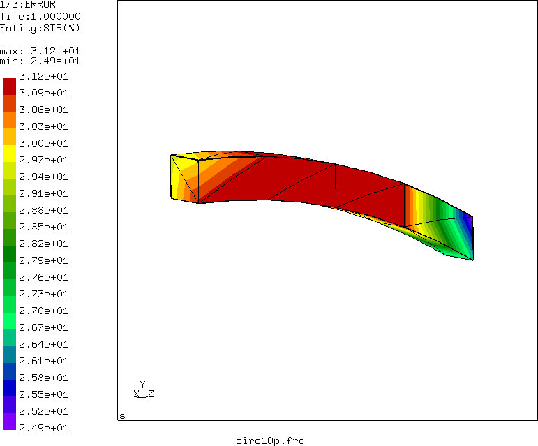
The value of the error estimator is shown in Figure . Not
surprisingly, the error is quite high, up to 30 %.
In order to obtain better results, an automatic stress-based refinement is triggered by the *REFINE MESH,LIMIT=50 card. The field on which the refinement is based is listed underneath this card. “S” means that the Mises stress will be used. The Mises stress for this example reaches values of about 400 stress units, so a refinement of up to a factor of 8 is locally possible (a refinement limit of 50. was chosen). In the current version of CalculiX up to three iterations are performed, each of which allows for a refinement by a factor of two. The refinements are always applied to a version of the original mesh in which any quadratic elements are replaced by linear ones (C3D10 by C3D4), i.e. the middle nodes are not taken into account. The results of these refinement iterations are stored as input decks (containing only the mesh) in files finemesh.inp0, finemesh.inp1 and finemesh.inp2. After generating the mesh stored in finemesh.inp2, the program generates midnodes for all elements if the input deck contained at least one quadratic element. All nodes are subsequently projected onto the faces of the original mesh. This means that the geometry is basically described by the outer surface of the mesh in the input deck. Elements in the input deck other than tetrahedral elements remain untouched. The resulting projected mesh is stored as input deck in jobname.fin. It contains only the refined mesh (nodes and elements).
Running the circ10p input deck and reapplying the necessary boundary and
loading conditions (this has to be done by hand) leads to the input deck
cric10pfin.inp (also part of the CalculiX test examples). Running this deck
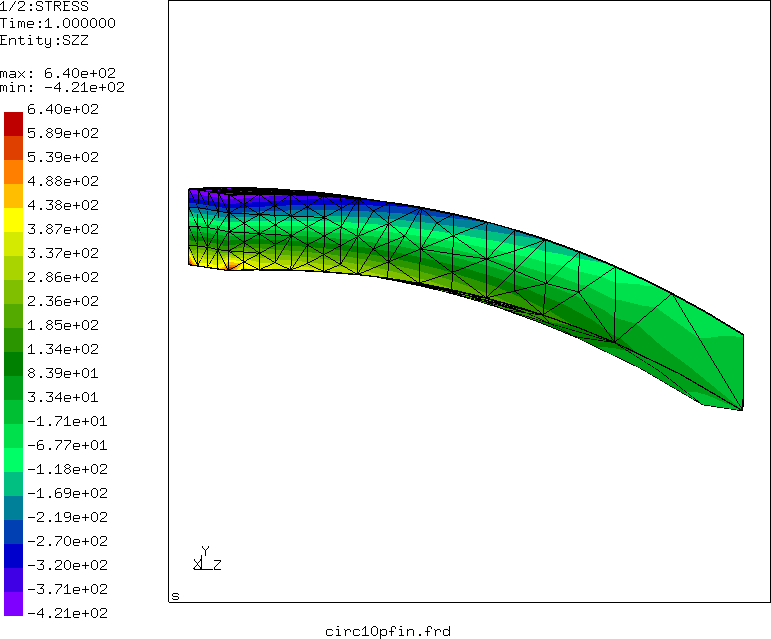
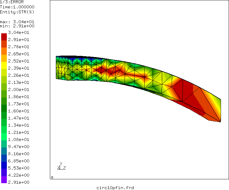
leads to the normal z-stresses in Figure and the error in Figure .
The mesh has been refined near the left face of the beam, where the stresses were highest. The resulting elements are quadatic elements and the curvature of the original mesh has been nicely kept.
The compressive stresses are slightly increased, while the tensile stresses are now much more localized about the nodes fixed in y-direction. The overall level, however, is similar. The stress error is about the same as for the coarse mesh, however, at those locations where the stress is high, the error is now low, about 5 % instead of 30 %. These are the locations of interest.
The output for the reaction forces in the .dat file looks like:
 total force (fx,fy,fz) for set FIX and time  0.1000000E+01

        3.221013E-12 -9.000000E+00  7.356782E-12


 statistics for surface set SFIX and time  0.1000000E+01

   total surface force (fx,fy,fz) and moment about the origin(mx,my,mz)

    1.512388E-01 -9.252627E+00 -7.227514E-01  7.175724E+01  1.563390E-01 -4.206416E+00

   center of gravity and mean normal

    5.000000E-01  5.000000E-01  4.014218E-19 -4.263022E-20  4.286885E-20 -1.000000E+00

   moment about the center of gravity(mx,my,mz)

    7.211862E+01 -2.050367E-01  4.955169E-01

   area,  normal force (+ = tension) and shear force (size)

    6.000000E+00  7.227514E-01  9.253863E+00
The nodal output is again very accurate, while the section output has clearly improved: the total reaction force is now -9.25 force units, the moment about the center of gravity is 72.12 [force][length]. The finer mesh leads to more accurate nodal stresses, which are the ones which have been used to determined the section forces.