Next: Frequency calculation of a Up: Simple example problems Previous: Cantilever beam Contents
Let us consider the beam from the previous section and determine its
eigenfrequencies and eigenmodes. To obtain different frequencies for the
lateral directions the cross section is changed from 1x1 to 1x1.5. Its length
is kept (8 length units). The input deck is very similar to the one in the
previous section, Figure ![[*]](crossref.png) . The full deck is part of the
test example suite (beamf2.inp).
. The full deck is part of the
test example suite (beamf2.inp).
The only significant differences relate to the steps. In the first step the
preload is applied in the form of compressive forces at the end of the
beam. In each node belonging to set LAST a compressive force is applied with
a value of -48.155 in the positive z-direction, or, which is equivalent, with
magnitude 48.155 in the negative z-direction. The second step is a frequency
step. By using the parameter PERTURBATION on the *STEP keyword card the user
specifies that the deformation and stress from the previous static step
should be taken into account in the subsequent frequency calculation. The
*FREQUENCY card and the line underneath indicate that this is a modal analysis
step and that the 10 lowest eigenfrequencies are to be determined. They are
automatically stored in the .dat file. Table
shows these eigenfrequencies for the beam without and with
preload together with a comparison with ABAQUS (the input deck for the modal
analysis without preload is stored in file beamf.inp of the test example suite). One notices that due to the
preload the eigenfrequencies drop. This is especially outspoken for the
lower frequencies. As a matter of fact, the lowest bending eigenfrequency is
so low that buckling will occur. Indeed, one way of determining the buckling
load is by increasing the compressive load up to the point that the lowest
eigenfrequency is zero. For the present example this means that the buckling
load is 21 x 48.155 = 1011.3 force units (the factor 21 stems from the fact
that the same load is applied in 21 nodes). An alternative way of determining
the buckling load is to use the *BUCKLE keyword card. This
is illustrated for the same beam geometry in file beamb.inp of the test suite.
| without preload | with preload | ||
| CalculiX | ABAQUS | CalculiX | ABAQUS |
| 13,096. | 13,096. | 705. | 1,780. |
| 19,320. | 19,319. | 14,614. | 14,822. |
| 76,840. | 76,834. | 69,731. | 70,411. |
| 86,955. | 86,954. | 86,544. | 86,870. |
| 105,964. | 105,956. | 101,291. | 102,148. |
| 162,999. | 162,998. | 162,209. | 163,668. |
| 197,645. | 197,540. | 191,581. | 193,065. |
| 256,161. | 256,029. | 251,858. | 253,603. |
| 261,140. | 261,086. | 259,905. | 260,837. |
| 351,862. | 351,197. | 345,729. | 347,688. |
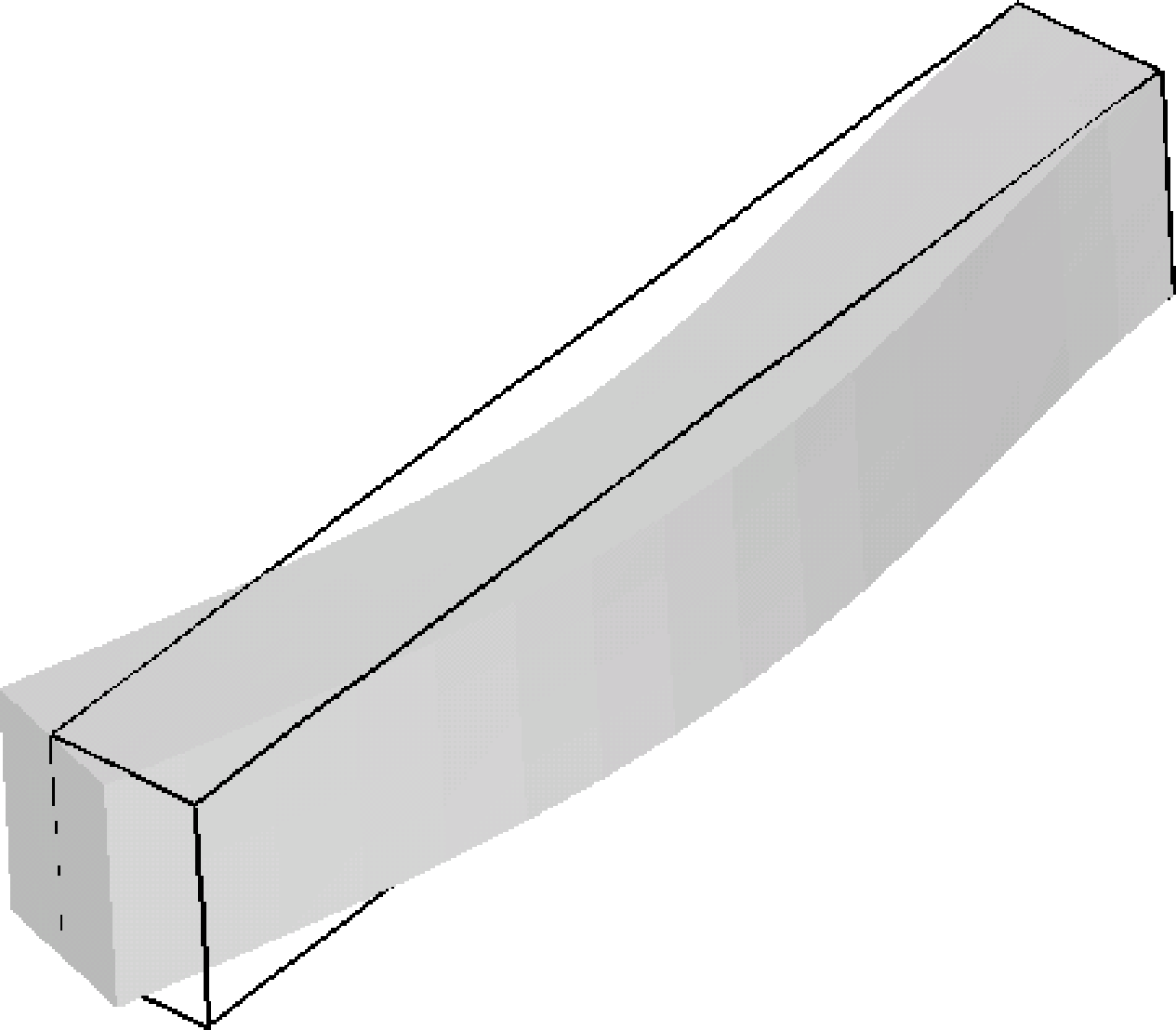
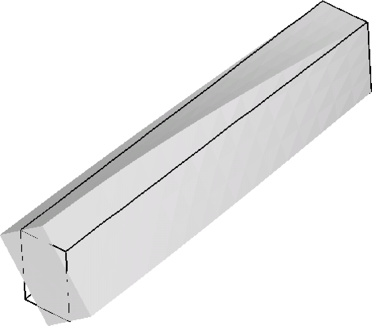
Figures and show the deformation of the second bending mode across the
minor axis of inertia and deformation of the first torsion mode.