Next: split Up: Commands Previous: setr Contents
   'shpe' <name|!> ['pln' <P1> <P2> <P3>] |
                   ['cyl' <P1> <P2> <R1>] |
                   ['con' <P1> <P2> <R1> <R2>] |
                   ['tor' <P1> <R1> <P2> <R2>] |
                   ['sph'] <P1> <R1>]
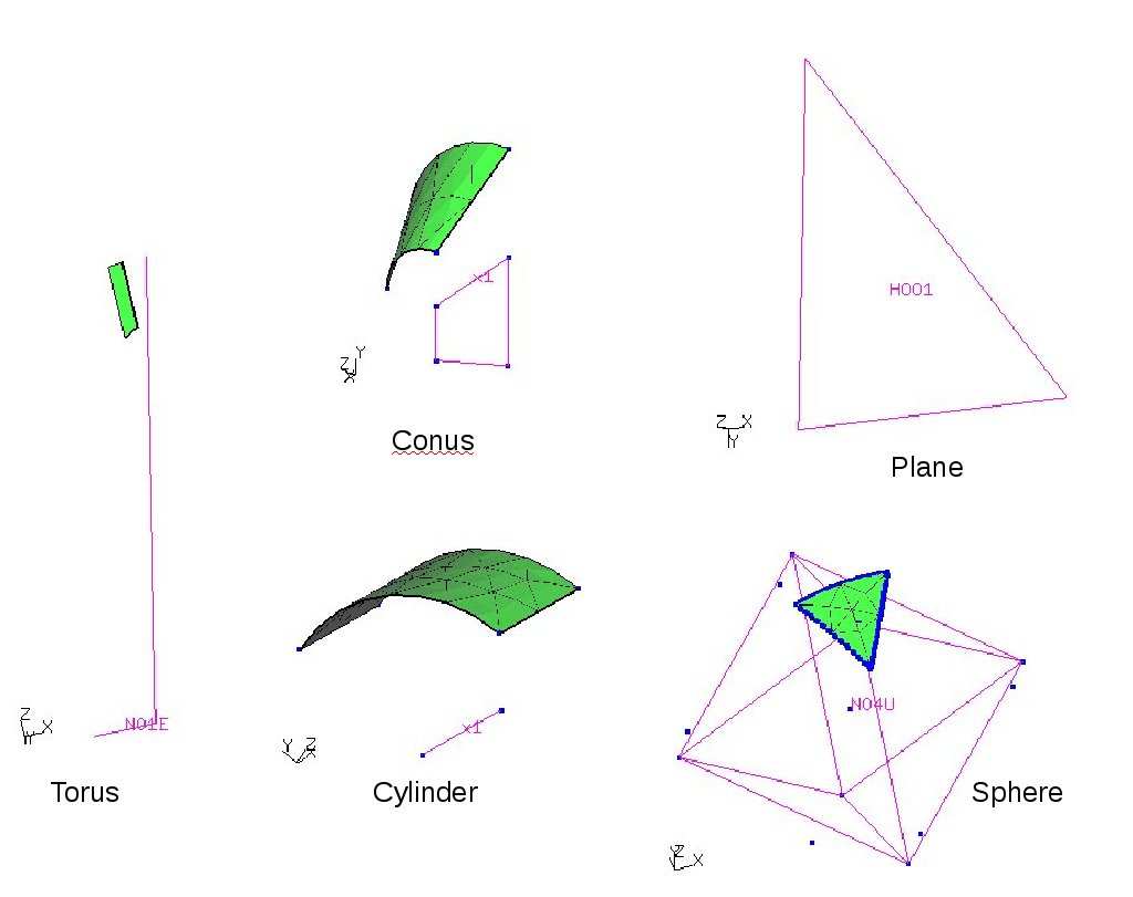
This keyword is used to create a shape which can be used to define the interior of surfaces or to be used as a target for projections (see proj) or to split entities (see split). REMARK: So far only the plane shape can be used for all kinds of projections and splitting. The other types can not be used for splitting and only the normal projection is implemented for them.
A plane shape is defined with the parameter “pln” followed by the names of three points:
shpe H001 pln P1 P2 P3
A cylinder can be defined by
shpe H001 cyl P1 P2 10.5
were 10.5 is the radius. A cone can be defined by
shpe H001 con P1 P2 10.5 2.
were 10.5 is the radius at point P1 and 2. at point P2. A torus can be defined by
shpe H001 tor P1 10.5 P2 2.0
were 10.5 is the radius at point P1. Point P2 lies on the torus axis and 2.0 is the radius of the tube. A sphere can be defined by
shpe H001 sph P1 10.5
were 10.5 is the radius at point P1. If automatic name generation is desired, then use ”!” instead of a name. See also “qshp” for the mouse controlled definition of shapes. It should be mentioned that all shapes are actually nurbs and that internally all nurbs which are used by surfaces are actually referenced by a shape as an interface.
Remark: A further shape type exists which links a nurbs to a surface definition. Such a shape will be automatically generated when a nurbs is finished by the “END” parameter using the same name as the nurbs. This shapes will not be written to a file but using the prnt command will list them:
shpe N001 NURS N001